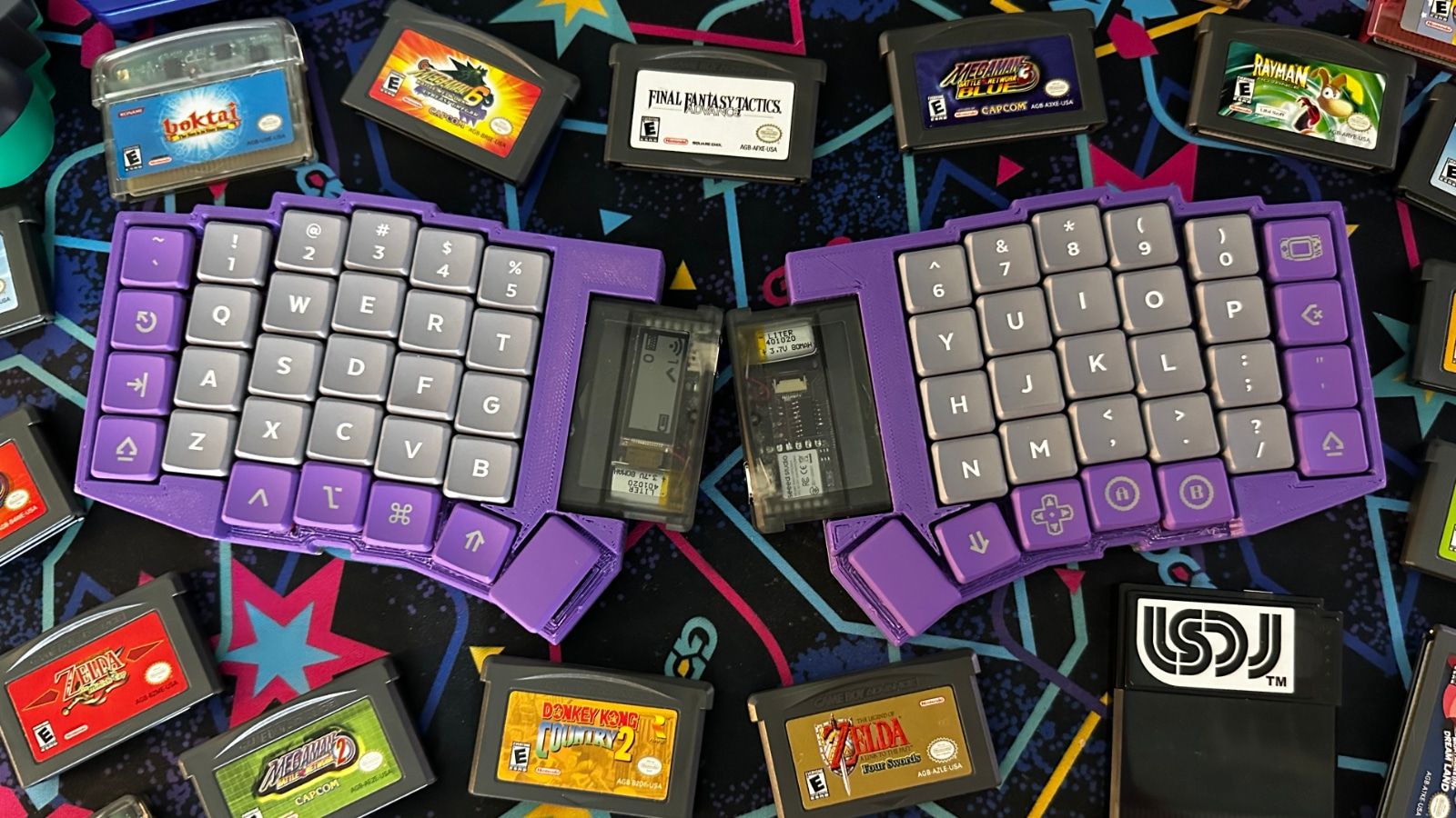
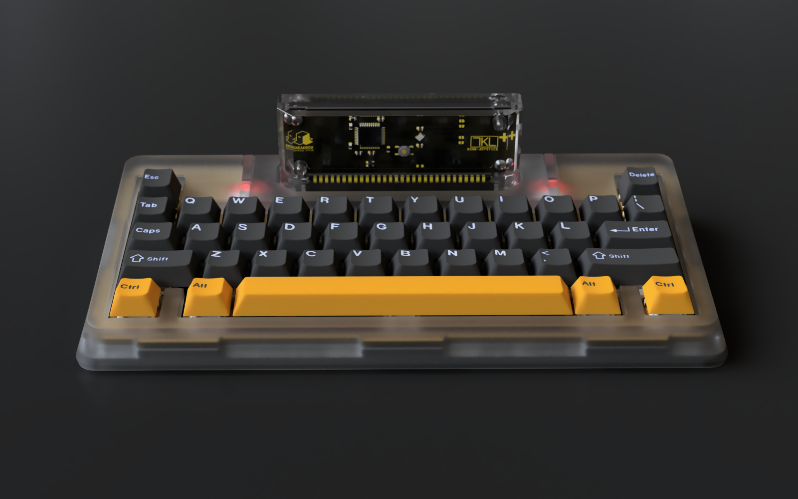
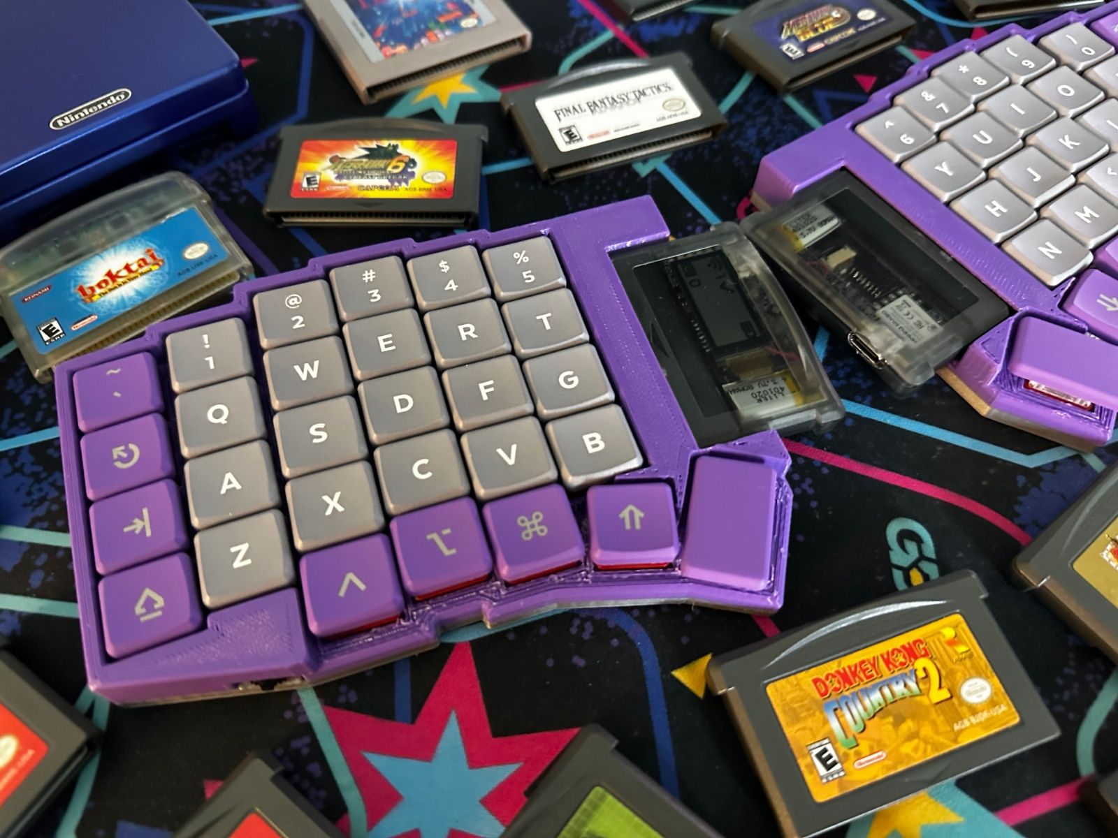
Welcome to my latest keyboard design! The TypeBoy is a fairly standard split ergonomic keyboard with a very non-standard microcontroller setup. Your eyes don't deceive you: This is a keyboard that needs a Game Boy Advance cartridge to function.
More specifically, it needs a TypePak! I've been spending a lot of time in the Ergogen keyboard layout generator lately, and I recently finished building a Sanni Open Source Cartridge Reader. These two worlds collided in my head and it dawned on me that a keyboard's microcontroller stack could probably fit in the shell of a Game Boy cartridge. A bit of tinkering in KiCAD later, and suddenly this monstrosity the TypePak was born.
The TypePak
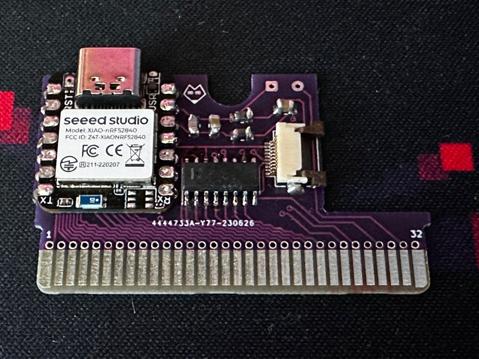
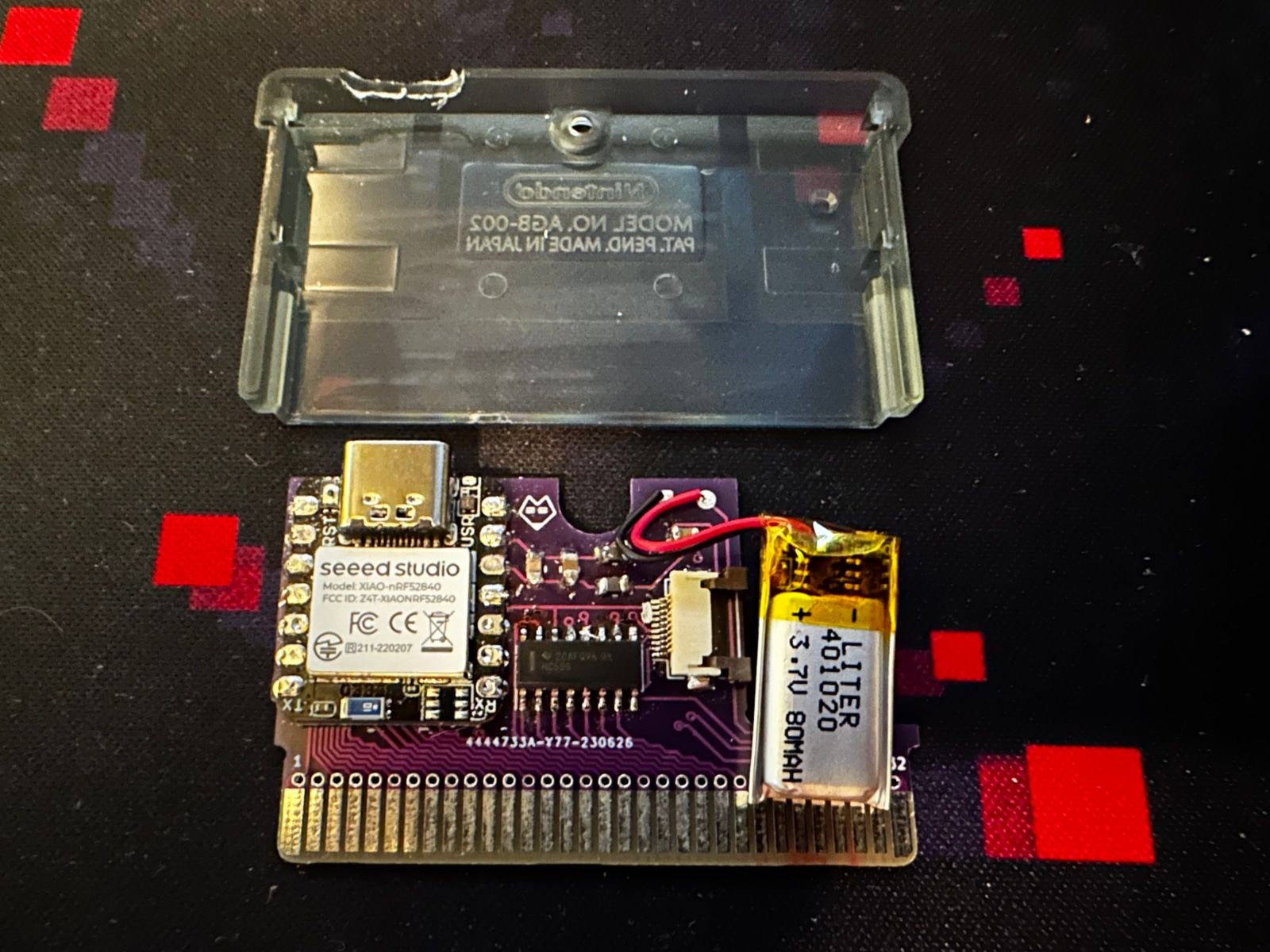
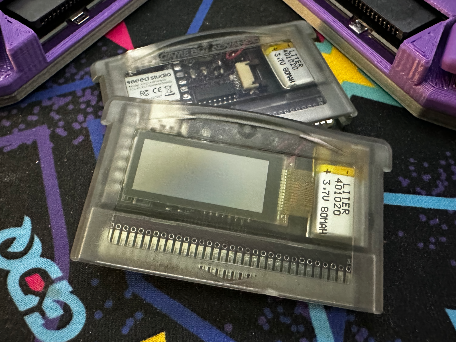
The TypePak is a custom keyboard controller PCB housed inside of an aftermarket Game Boy Advance cartridge shell. It features Bluetooth connectivity, ZMK support, a low-power monochrome display, a built in LiPo battery, 9 GPIO pins, and 8 dedicated output pins. Simply slot the TypePak into a keyboard with a compatible Game Boy cartridge slot, flip the power switch, and you've got yourself a working wireless keyboard. (After flashing the appropriate firmware and keymap, naturally.)
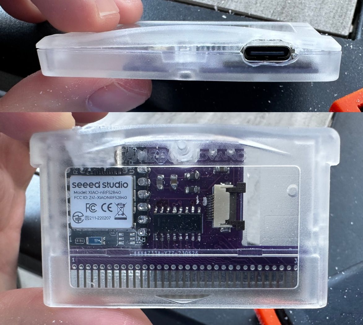
To little surprise, this is all pulled off thanks to the nRF52840 system on a chip. The nRF52840 is the heart of the popular Nice!Nano microcontroller, and boasts support for the wireless keyboard firmware ZMK. While the TypePak technically could have used a bare nRF52840 module, that would have required building out a decent amount of support hardware such as a USB-C port and battery charging circuitry. Instead, I opted to leverage the petite Seeedstudio XIAO nRF52840 microcontroller. (Affectionally called the "XIAO BLE" by folks who don't feel like memorizing a random five digit number.) This compact microcontroller has everything you need for a keyboard built into one small package, and it almost fits inside of a Game Boy Advance cartridge.
One of the downsides of the XIAO nRF52840 over the Nice!Nano is its relatively small number of exposed GPIO pins. The XIAO has just enough pins to power a small split keyboard, but the TypePak would be limited in the context of larger split boards or unibody builds. To rectify this, the TypePak also includes a 74HC595 shift register. This provides the TypePak with 8 dedicated output pins to use for columns in a keyboard matrix. Pair that with 9 free GPIO pins on the XIAO BLE, and you've got plenty of room for rows, columns, and other ancillary hardware.
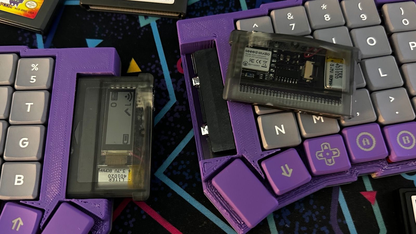
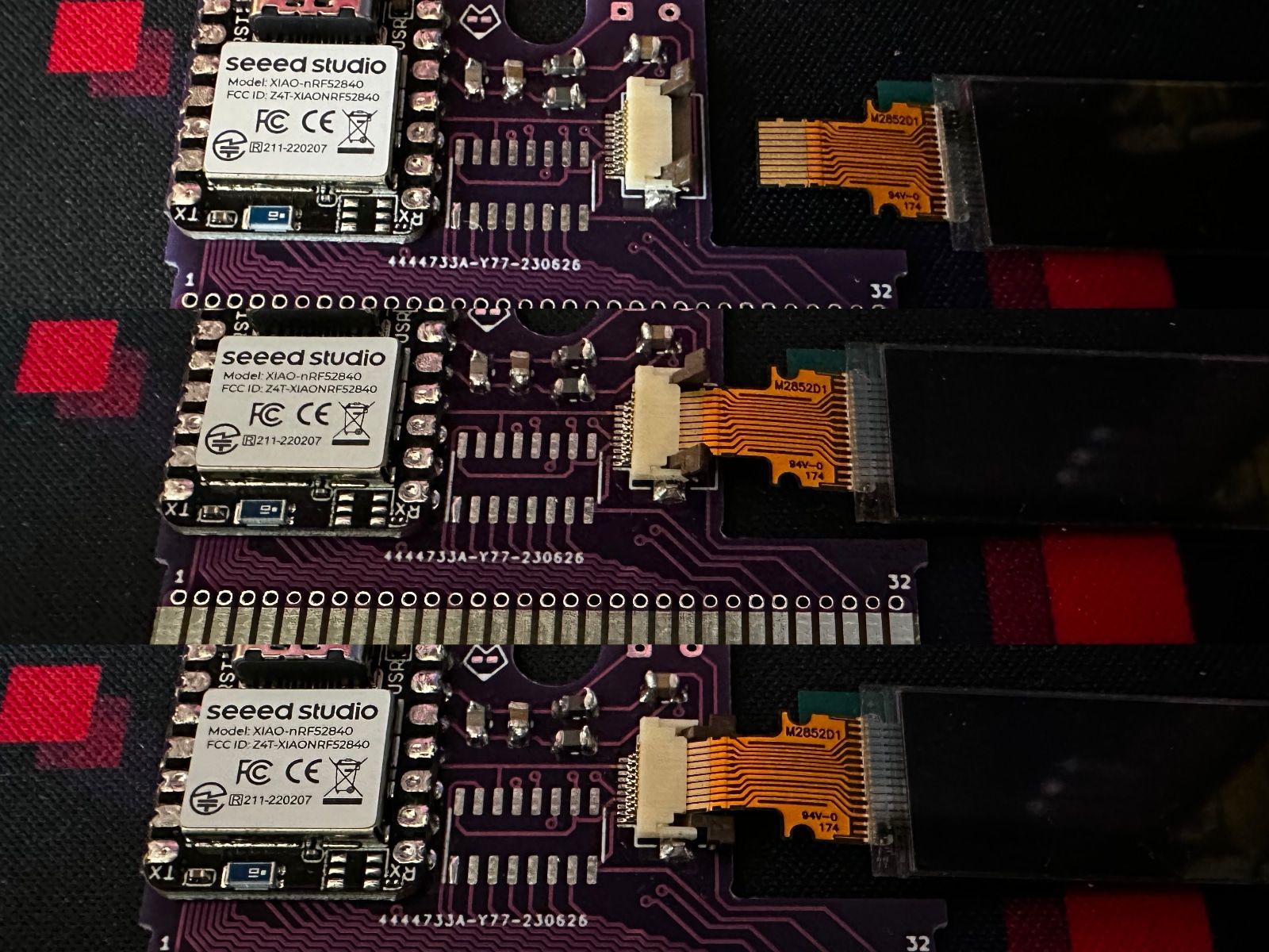
The other prominent component on the TypePak is a LS011B7DH03 Sharp Memory Display. This is the same 160x68 monochrome "transflective LCD" used on the Nice!View. There's not quite enough space in the cartridge for a proper Nice!View module, so the TypePak instead provides a ribbon cable connector and acts as a breakout board for a raw LS011B7DH03 display.
Finally, the TypePak has a 401020 LiPo battery soldered directly underneath the PCB. (Fun fact, the model number of these batteries tells you the dimensions. The 401020 is 40mm x 10mm x 20mm.) This battery is slightly smaller than the batteries you usually find tucked underneath an Arduino Pro Micro. It has 80 mAH of power compared to the typical 110 mAh LiPos. Thankfully these smaller batteries still have enough power to be reasonably useful. The main half of the TypeBoy gets about a week of battery life, while the secondary side of the keyboard should last you about two months. Just plug the left side in on Sunday nights and you should be fine.
All of these components are held together by a small custom PCB. The Game Boy cartridge slot expects PCBs to be between 0.8mm and 1mm thick. Building a 0.8mm thick PCB gives you a tiny sliver more room when building your keyboard, but some PCB manufacturers charge extra for non-standard colors on thin boards. Thankfully 1mm boards work just as well if you're going for a particular aesthetic. The 1mm PCBs also help provide a bit more friction to keep the cartridge in the slot a little better than the 0.8mm PCBs if you're planning on doing a lot of traveling with the TypeBoy.
The TypePak Pinout
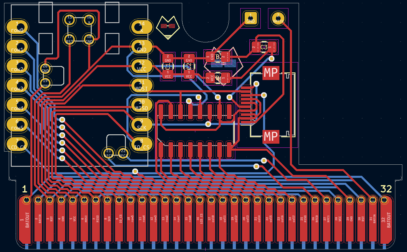
A Game Boy cartridge has 32 pins on its edge connector. The XIAO nRF52840 and the shift register have a total of 26 pins. (This includes the reset and NFC pins on the underside of the XIAO nRF52840.) Rather than leave twenty precent of the TypePak's cartridge pins unused, several of the important pins are exposed on both ends of the cartridge's edge connector. The battery output, power pins, reset pins, and a few others are duplicated so that you can more easily route some of the support hardware on your keyboard PCB.
Speaking of which, the TypePak does not have a built in power switch or reset button of its own. (Technically the XIAO does have a reset button, but it's underneath the cartridge's plastic casing.) You'll need to create out these components on the keyboard itself. The whole idea of this setup is to evoke the stylings of a classic Game Boy, so a large chunky power switch is honestly a welcome addition.
This does give the TypePak a slight quirk. The battery isn't physically attached to the microcontroller unless the cartridge is plugged into a keyboard and its power switch is set to the on position. If you'd like to charge the keyboard, you can't just dangle the TypePak off of a USB outlet.
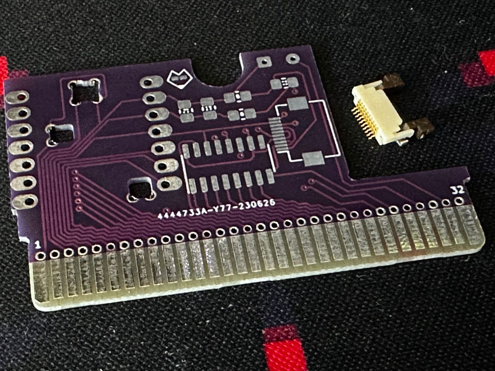
Every pin on the microcontroller is broken out onto the TypePak's edge connector. This includes pins that are used for components such as the Sharp Memory Display. If you decide not to include the display, or want to try adding on additional SPI devices, you shouldn't have any trouble getting to MISO, MOSI, SCK, and the LCB's CS pin.
The cartridge slot is easy enough to add to a keyboard design. Rather than adding two rows of through hole pins, you add one row of surface mount pads. The only quirk is on reversible PCB layouts. On the left keyboard the cartridge will be inserted with the first pin oriented towards the top of the PCB. On the right side of the keyboard, the last pin will be oriented towards the top of the PCB. The solution to this is to create a rainbow of via traces connecting the front pads to their mirrored counterpart on the back side. Thankfully the cartridge slot's width gives you a good amount of otherwise unused board space to trace these routes.
Building A TypePak
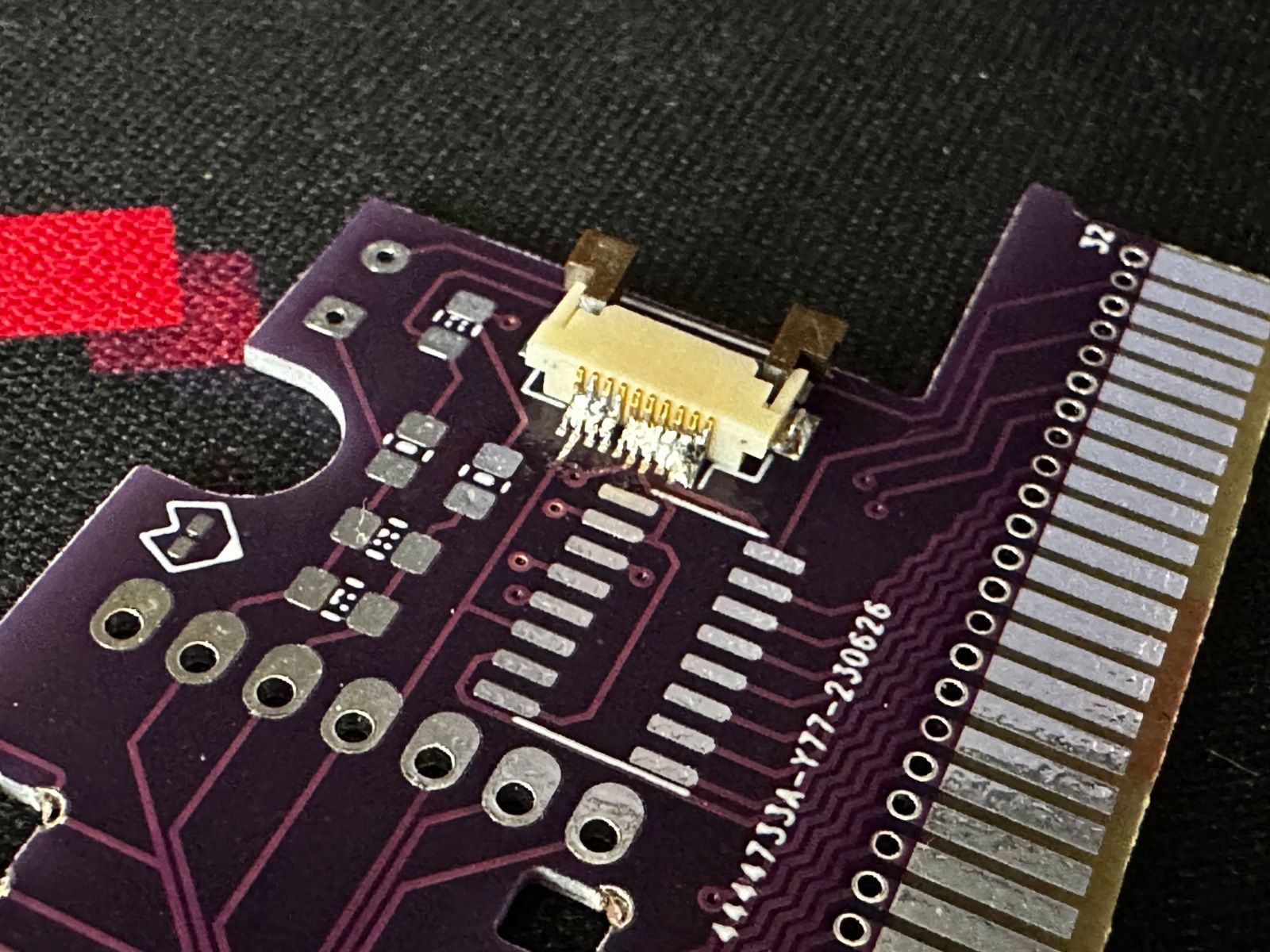
Assembling the TypePak PCB is a bit of an interesting challenge. The PCB needs to sit flush on the bottom cartridge shell, so this was my first PCB design to fully use surface mount components. I had experience with small surface mount diodes in the past, so the microcontroller and display capacitors weren't too much of an issue. Even the shift register isn't too tricky if you have steady hands. The display connector however...
This component is not a beginner-friendly soldering job. It has 0.5mm wide pins with a 0.5mm gap between them. If you haven't used solder flux and solder wick in the past, this project will teach you their usefulness.
Solder flux helps promote bonding between wires and pads. It prevents solder from clumping up, and lets you move excess solder around more easily. Even then, you're likely to get some bridging between pads.
That's where solder wicks come in. They can help remove excess solder from a board and clean up uncooperative shorts.
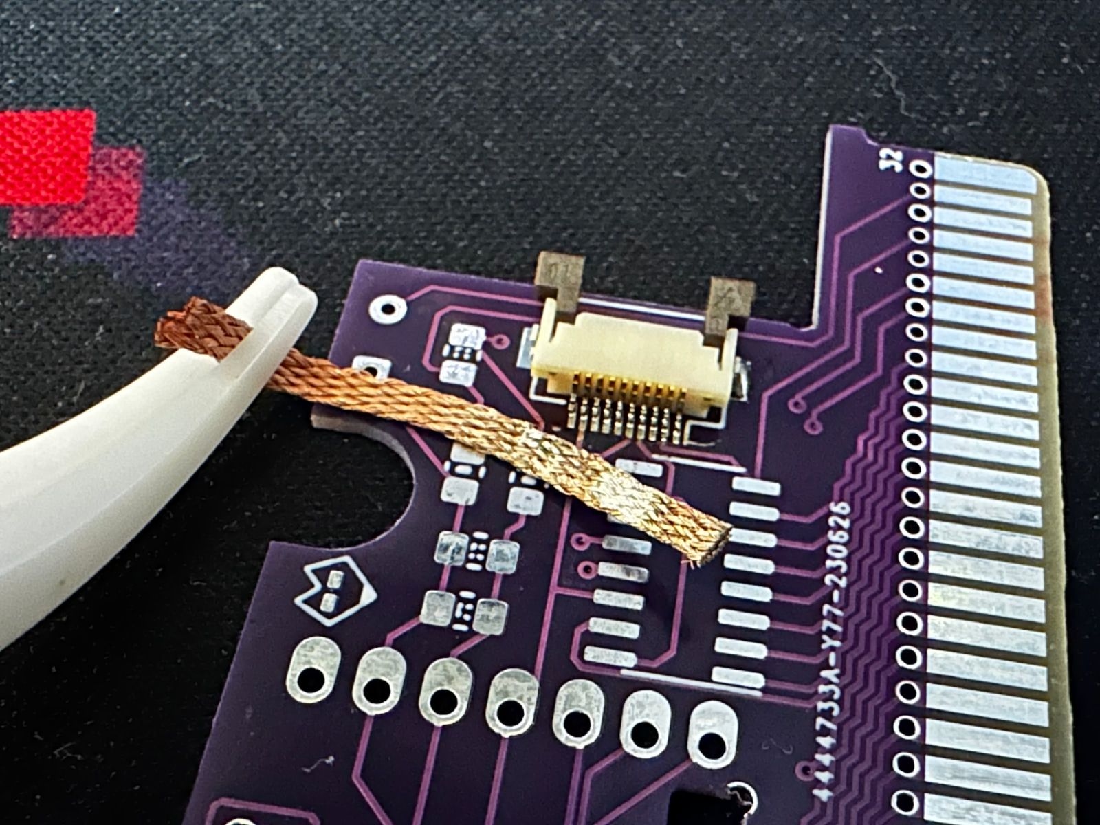
After some patient soldering, wicking, re-soldering, and additional wicking, you should be able to get the display connector situated cleanly. Honestly, I'm a little upset with myself for not getting on board with solder wicks sooner.
Besides taking it slow, the most important part of soldering the display connector is making sure all of it's pins are aligned. It has two mounting pads on the side, so you can solder one of those pads into place before tackling the actual data pins. JLCPCB and some other PCB fabs also have the display connector in their parts library. If it's not prohibitively expensive, I may look to just have my PCB fab deal with these connectors in the future. Once you've got everything soldered, make sure you use a continuity tester to make sure the pins aren't bridged anywhere.
After dealing with the display connector, the XIAO, capacitors, and shift register shouldn't be any issue. A bit of solder flux can help the shift register as well. Just solder one of the pins to anchor the rest into their properly aligned position. Everything else is just standard smd soldering. Maybe invest in some reverse action tweezers along with the flux and solder sick.
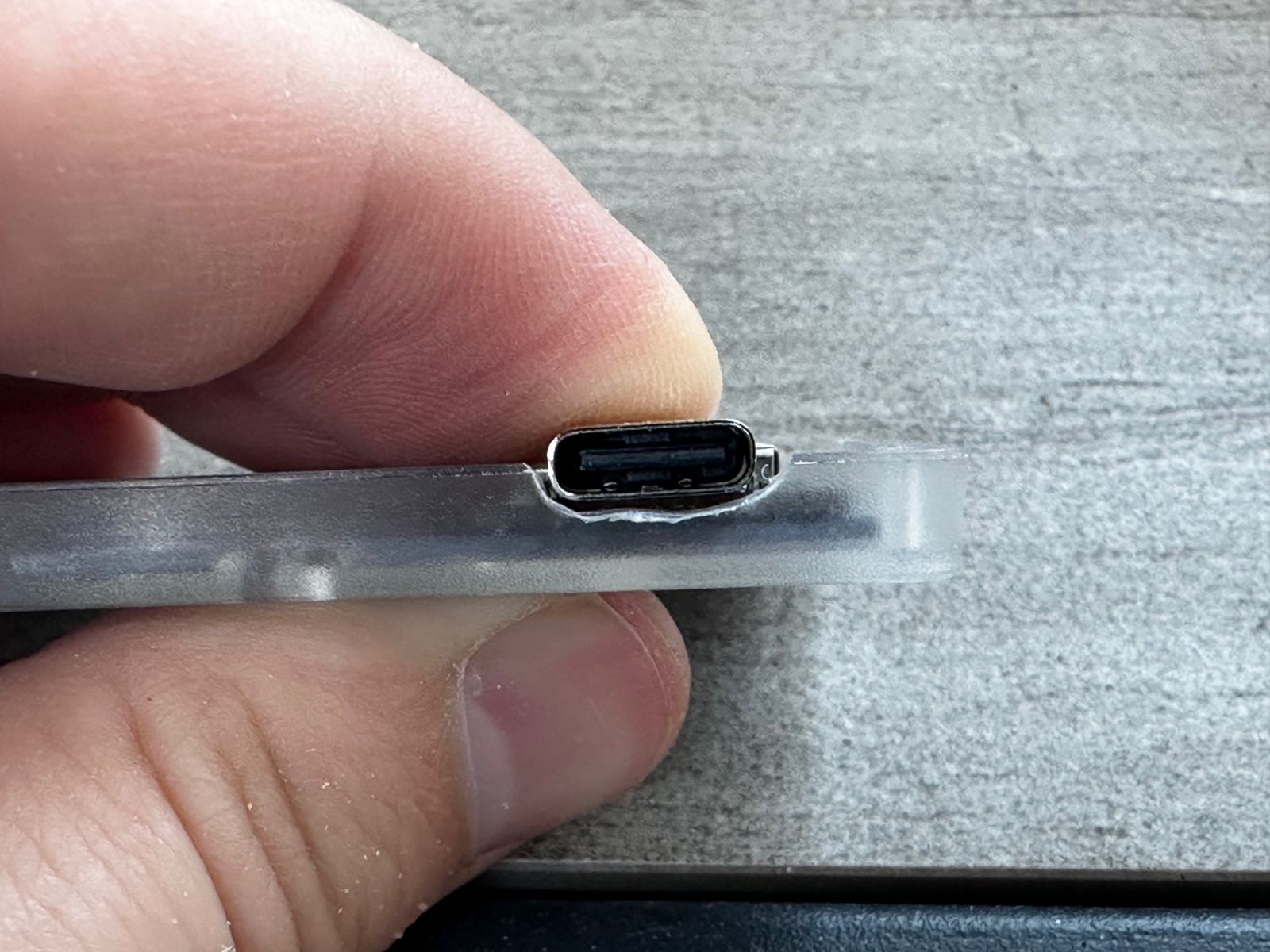
One you have everything but the battery soldered into place, you can start contemplating the cartridge shell. The side of the plastic shell will need a cutout for the TypePak's USB-C port, but we actually need to go a bit further than that. When I first mentioned the XIAO nRF52840, I said it almost fit in a GBA cartridge. Between the TypePak cartridge and the XIAO's PCB, the USB-C port is just a millimeter or so too tall. We'll also need to carve out some additional headroom for the USB-C port while creating a cutout for it.
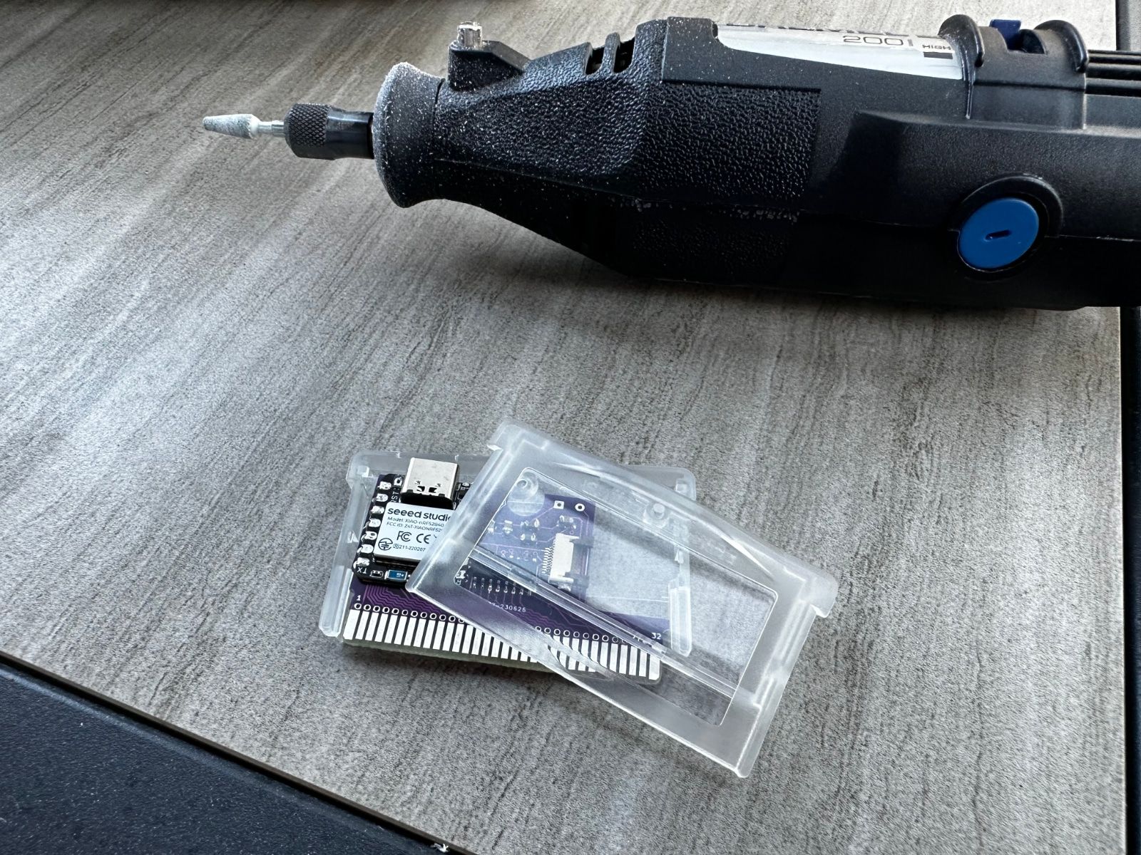
That's right, this is a project requiring some power tools.
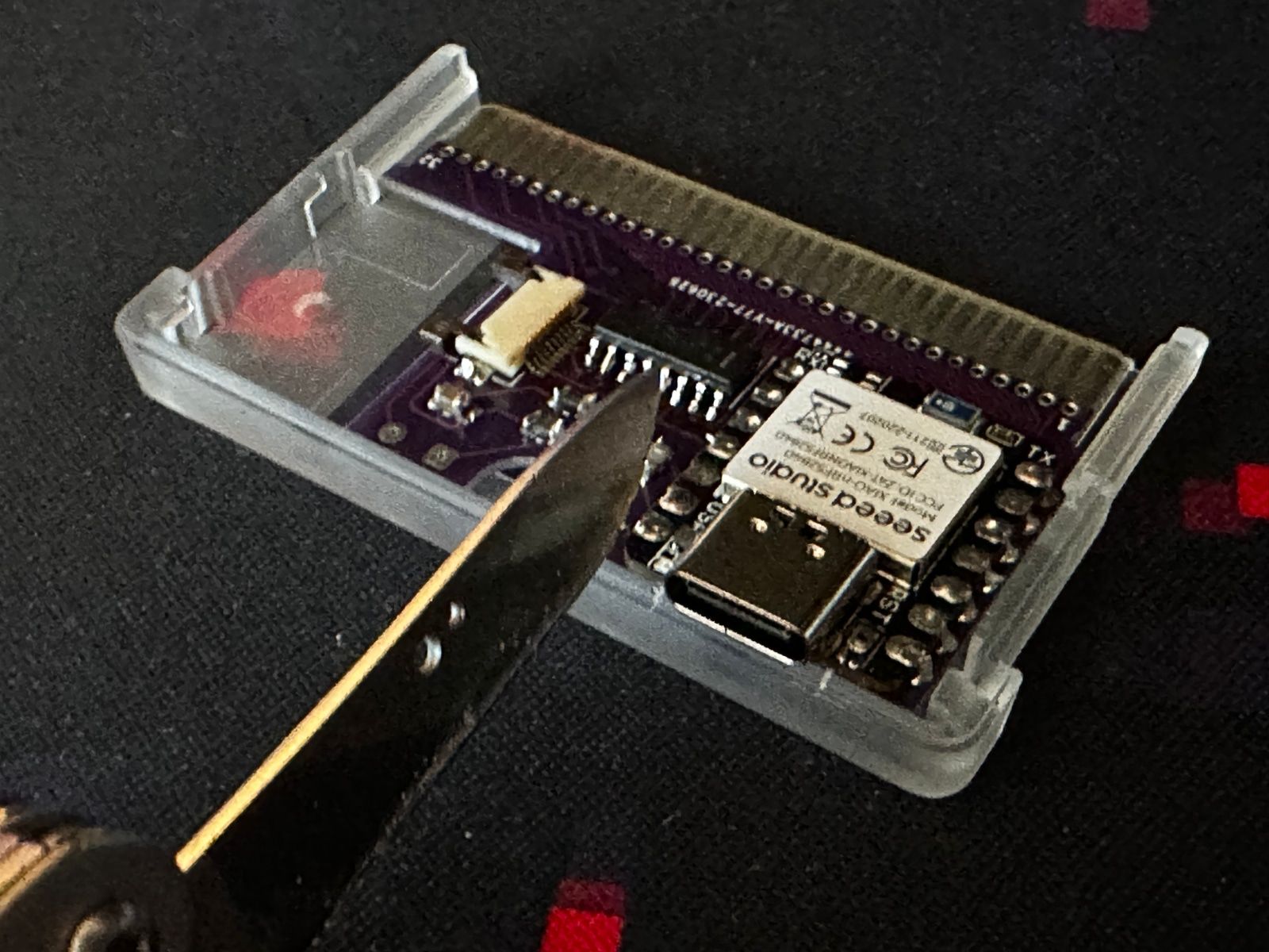
There's probably a few different ways of tackling this sort of cutout, but I personally opted for a Dremel and a clamp. Grab a face mask and protective eyewear for good measure. You're going to be kicking up a lot of plastic dust. The easiest way to keep track of what parts you need to remove is to make small scoring marks with a hobby knife while the PCB's in the case.
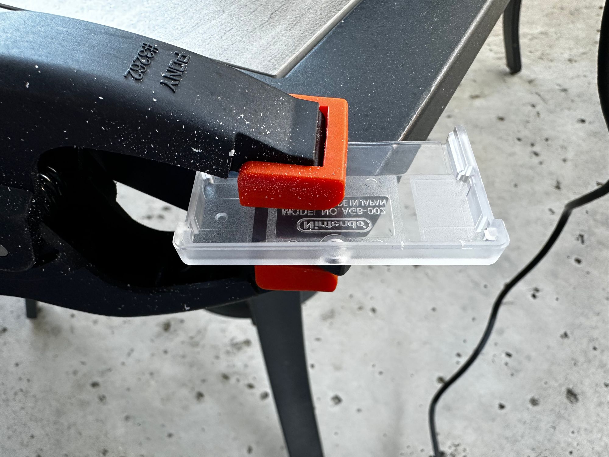
Remove the PCB, clamp one half of the cartridge shell down, sand a bit of the material away, unclamp the case, and reseat the PCB to see if it fits.
You'll want to repeat this process a half-dozen times. You can't add plastic back to the shell, so it's better to drill away too little than too much.
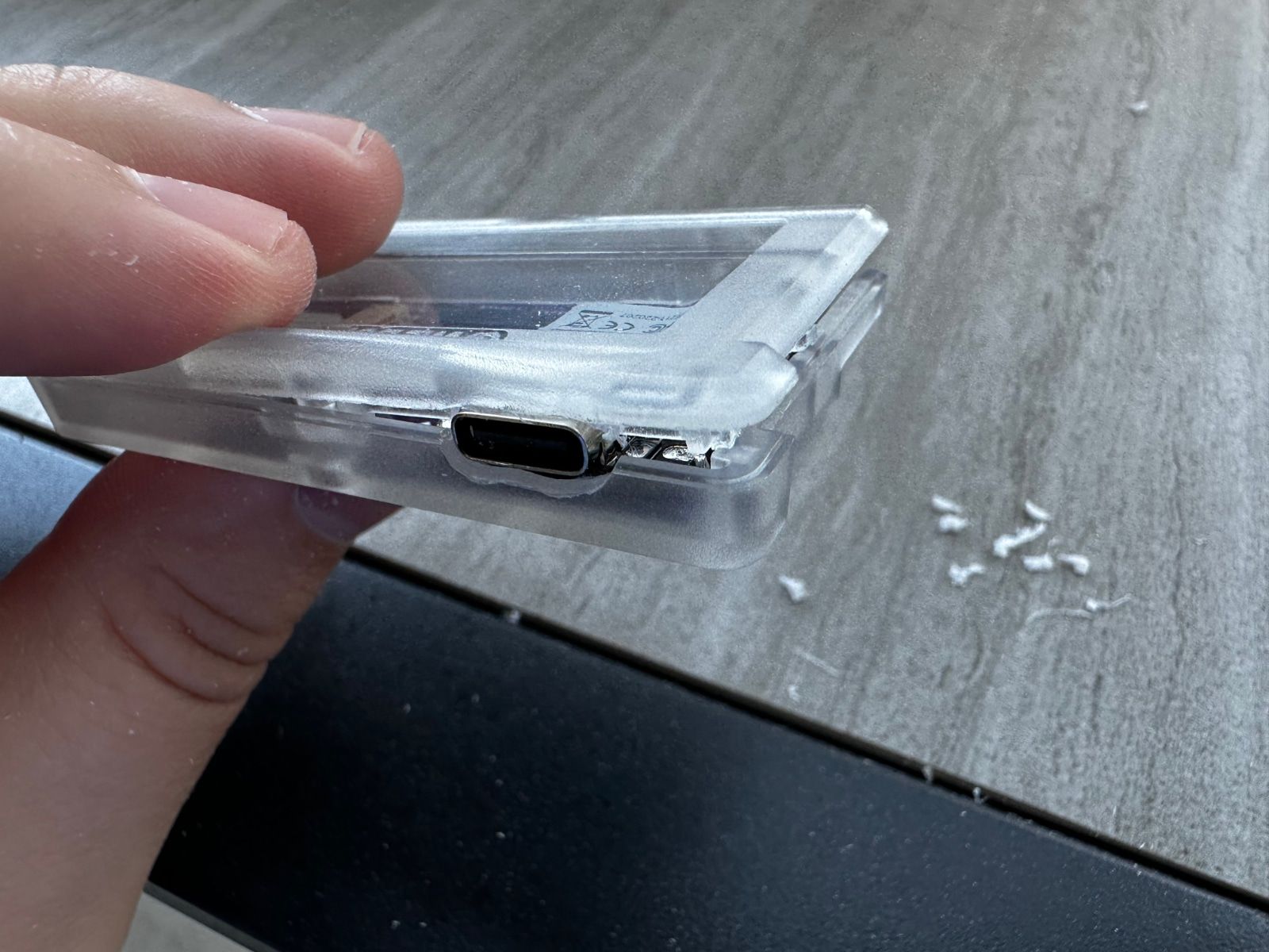
Once you've got the PCB sitting flush in the bottom piece, it's time to work on the top half. Drilling a side cutout for the USB-C port isn't enough here. You'll quickly find that the two halves of the case don't have enough room close.
My first instinct was to simply make a large rectangular cutout in the top of the cartridge shell. (You can see an example of this a bit later in this writeup.) Rather than completely taking the top off of the cartridge however, it's enough to simply shave off some of the plastic from inside the case. The cartridge is just thick enough that you can carve out the inside of the shell without actually disturbing the exterior of the shell.
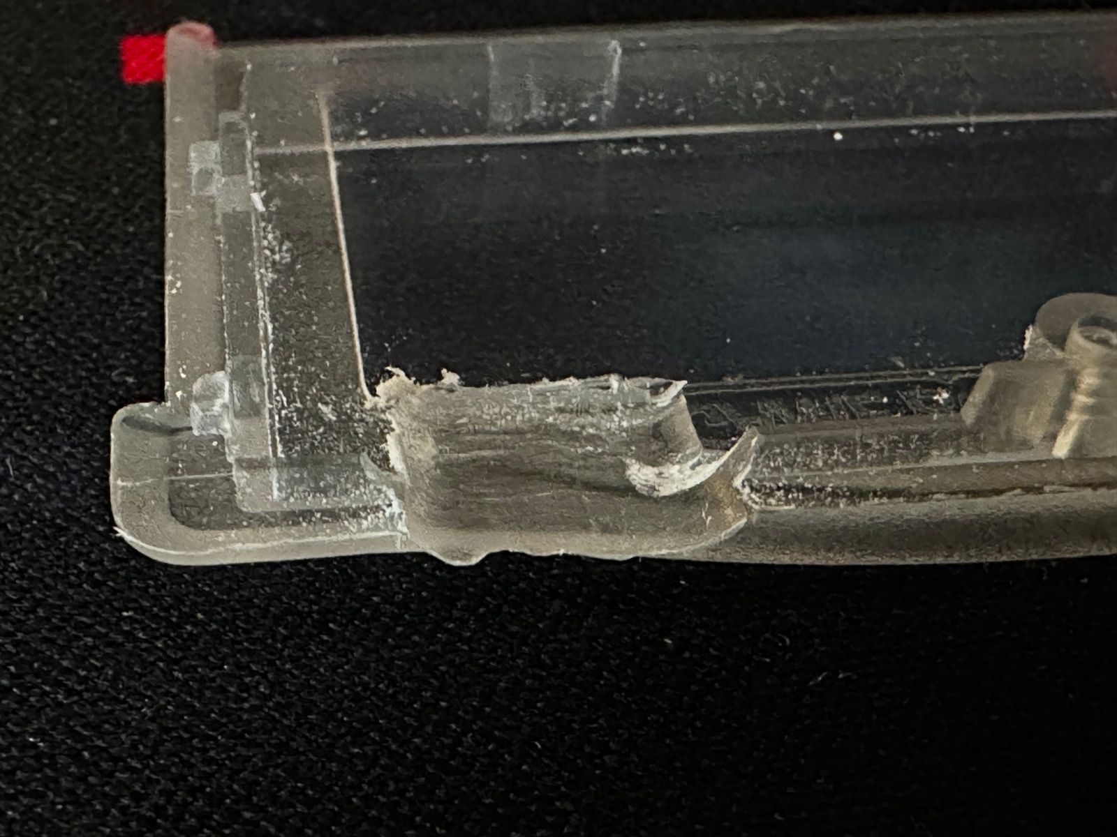
It's a tricky process and will require a few rounds of shaving, re-fitting, and shaving away again. In my experience, the end result hasn't been a perfect fit. The two halves are held together with two small plastic tabs on each side of the cartridge. After enough drilling, you should at least be able to get all four tabs to remain comfortably in place.
The center of the cartridge may bow out a bit, but there's also a screw that can help hold the cartridge together. There's a small gap in the cartridge if you know where to look, but it's not very noticeable on the transparent cartridge cases.
At this point we can go ahead and add the battery and close the cartridge up. In my experience however, it's pretty easy to accidentally leave a pin not fully soldered or have an accidental bridge somewhere. Rather than opening and closing the cartridge several times as you troubleshoot, now would be a good time to go and build your keyboard itself. The TypePak fits in a cartridge slot with the top half of the cartridge missing, so you can properly test everything over USB before continuing. If something doesn't work, it'll be easier to run some continuity tests before closing everything up.
Once you're happy that the keyboard and the TypePak are working, you can go ahead and solder the LiPo battery into place.
After that, carefully attach the Sharp Memory Display ribbon cable. Flip the latch up, slide the ribbon in over the top of the gray flap, and then push it back down.
Actually assembling the cartridge is... really tight. You need to slot the cartridge into place, slot the battery in beside it, and then do your best to fold the ribbon cable over so that the screen is pointing up at the cartridge's clear window. The process is a little tricky to photograph.
You might not get the screen 100% aligned with the window. I tried taping the screen down to the top shell, but that made it nearly impossible to actually attach the ribbon cable. In addition to needing to worry about the display while closing the two halves of the cartridge, you need to be mindful of the battery's position inside of the case. The LiPo battery has a tendency to slide up all the way to one side of the cartridge. The plastic lip of the battery likes getting pinched by the case as you try to close it.
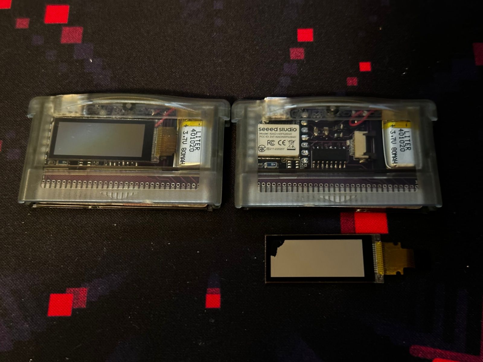
Once you get the two pieces together, you have a nice compact cartridge of keyboard computing. Hopefully. The first cartridge I built ended up crushing the display between the cartridge shell and the top of the XIAO. It cracked the display instantly before I even had a chance to feel any resistance. Your milage may vary, but thankfully the second cartridge came together a bit easier. You really only need one display for a split keyboard, so I just left the second display out for this particular build. Hopefully things go a bit smoother for you. Just take things slow and be mindful of the stress you're putting on the different components.
Now that we've got the TypePak built, we can turn our attention towards the TypeBoy.
The TypeBoy
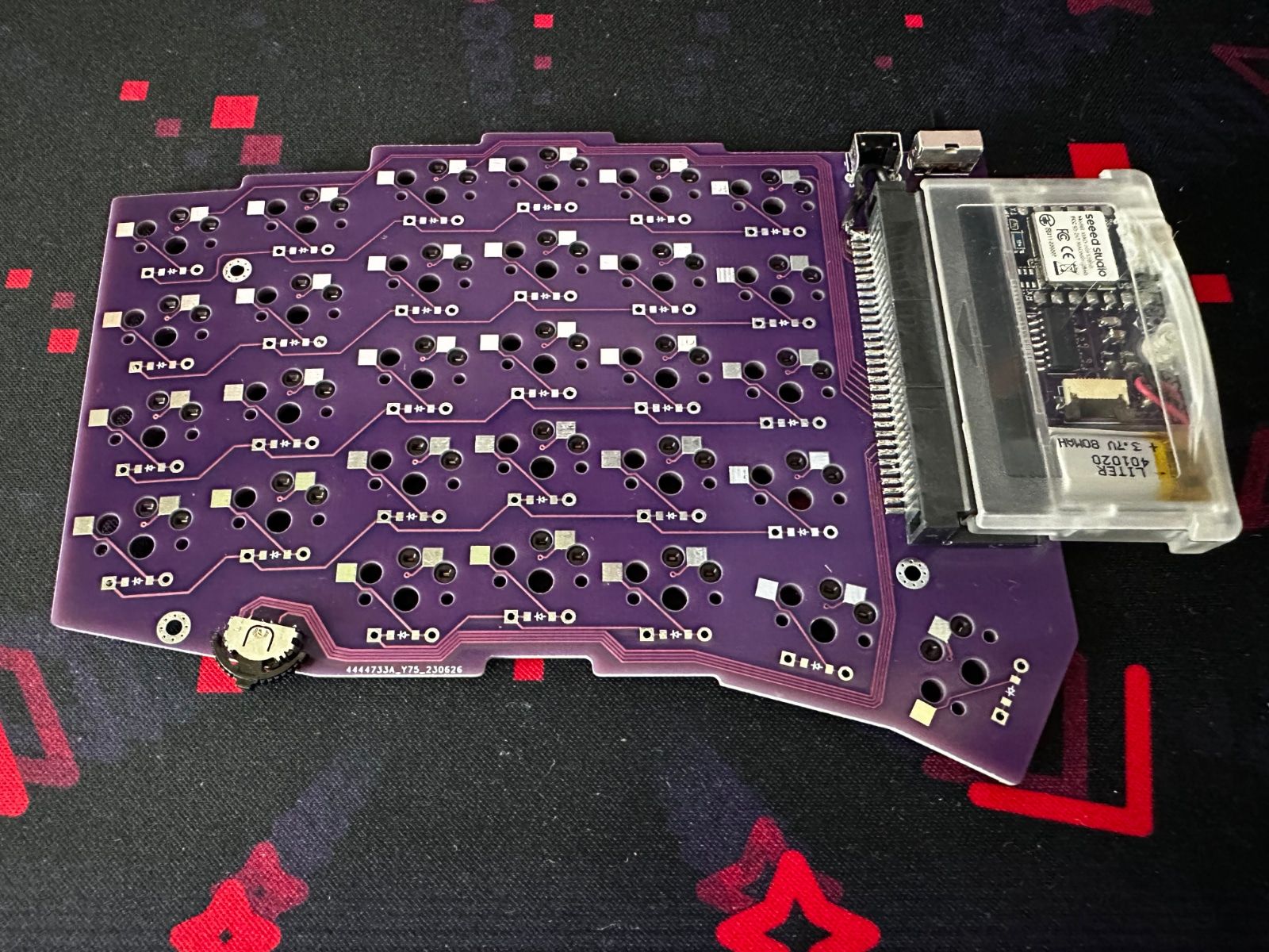
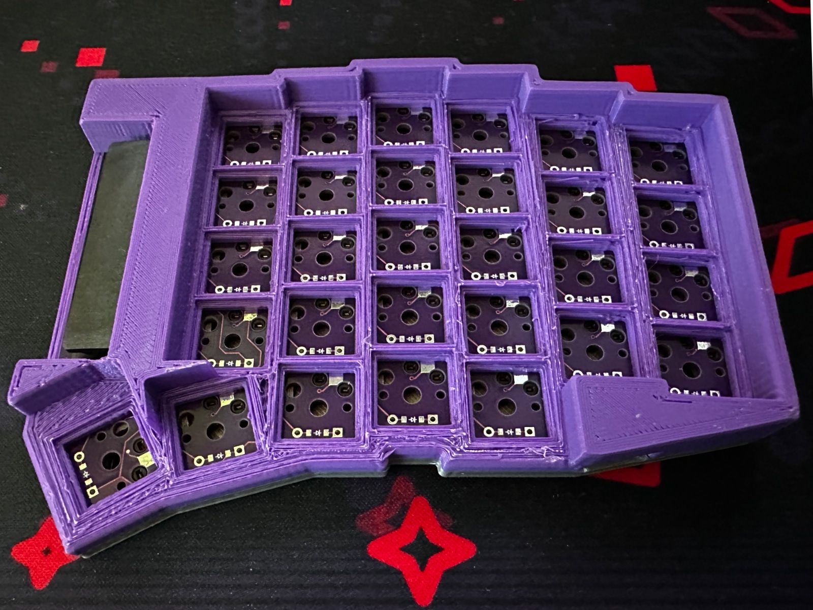
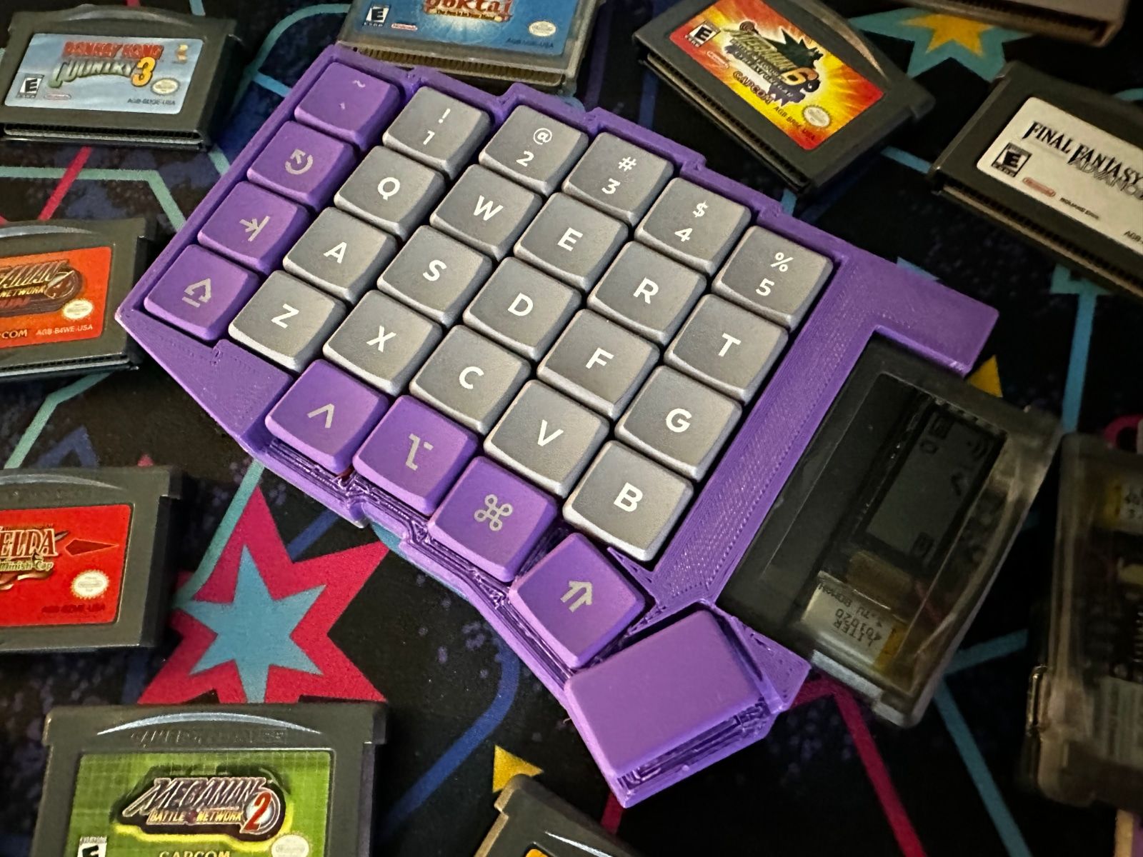
The TypeBoy is a fairly standard split keyboard with a 6x4+5 column staggered layout. If it looks familiar, that's because this is essentially a split version of the keyboard I designed for my Let's Design A Keyboard With Ergogen v4 series. I've fallen into a little bit of a rut with 58 key boards, but what can I say, I'm a sucker for dedicated number keys.
The most striking aspect of the TypeBoy is naturally the large Game Boy cartridge slot on the side. This component replaces the standard microcontroller stack, and takes up slightly more PCB space than your standard Pro Micro or Nice!Nano setup. The cartridge slot has two plastic mounting legs, so aligning and soldering the pins is a breeze. Well, it's a breeze after that display connector at least.
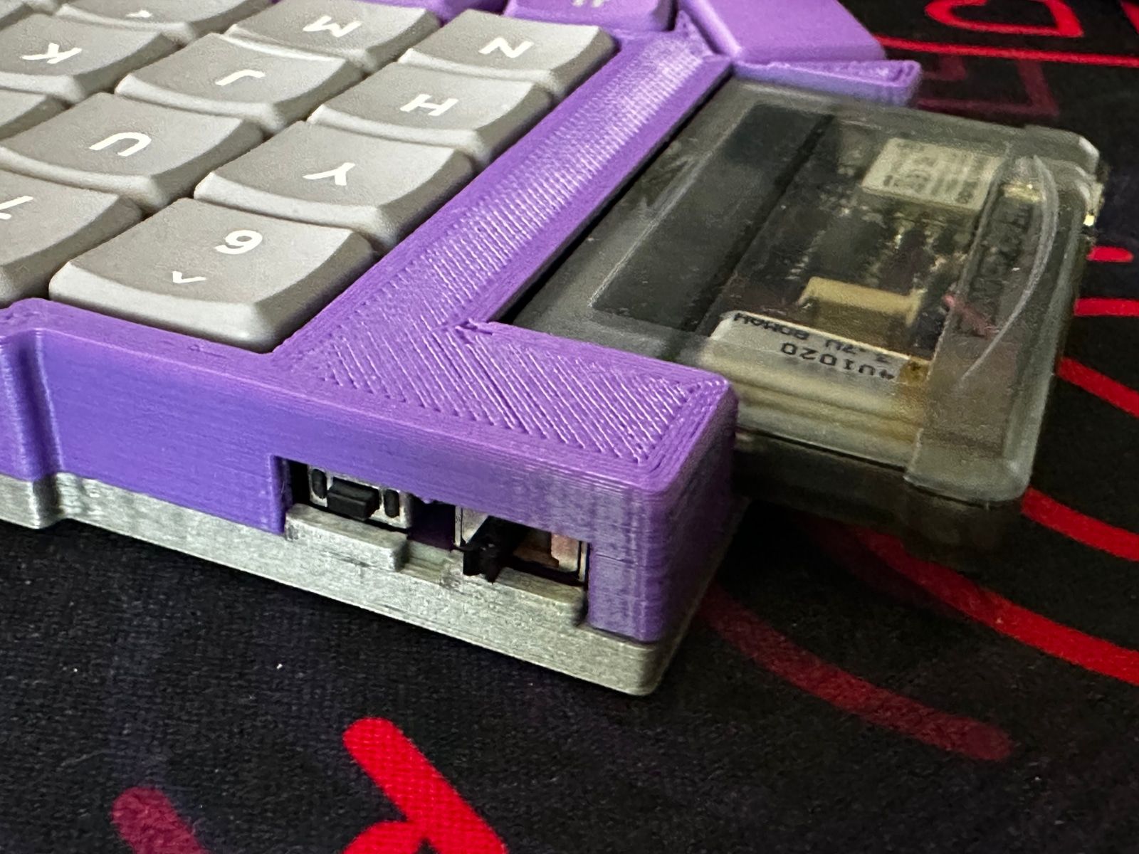
The keyboard building scene has several low profile slide switch and pushbutton options, but I was able to take advantage of some taller components on this particular build. Since the hardware's going to be nestled up against the already tell cartridge slot, I was able to use nice chunky power switches and reset buttons. Both of them are of the right angle variety. The right angle reset button is a bit anachronistic for a Game Boy, but the power switch hits all the right nostalgia notes.
Finally, mechanical keyboards often include rotary encoders. These knobs can't do anything that a hotkey on your keyboard couldn't handle, but they're popular for quickly adjusting the volume on one's PC. Wouldn't you know, there's one last piece of Game Boy hardware that we can pay homage to. Nintendo's handhelds have had a variety of volume wheels and contrast knobs over their lifetime. I did some digging and tried to find a low profile encoder that would be suitable for the TypeBoy.
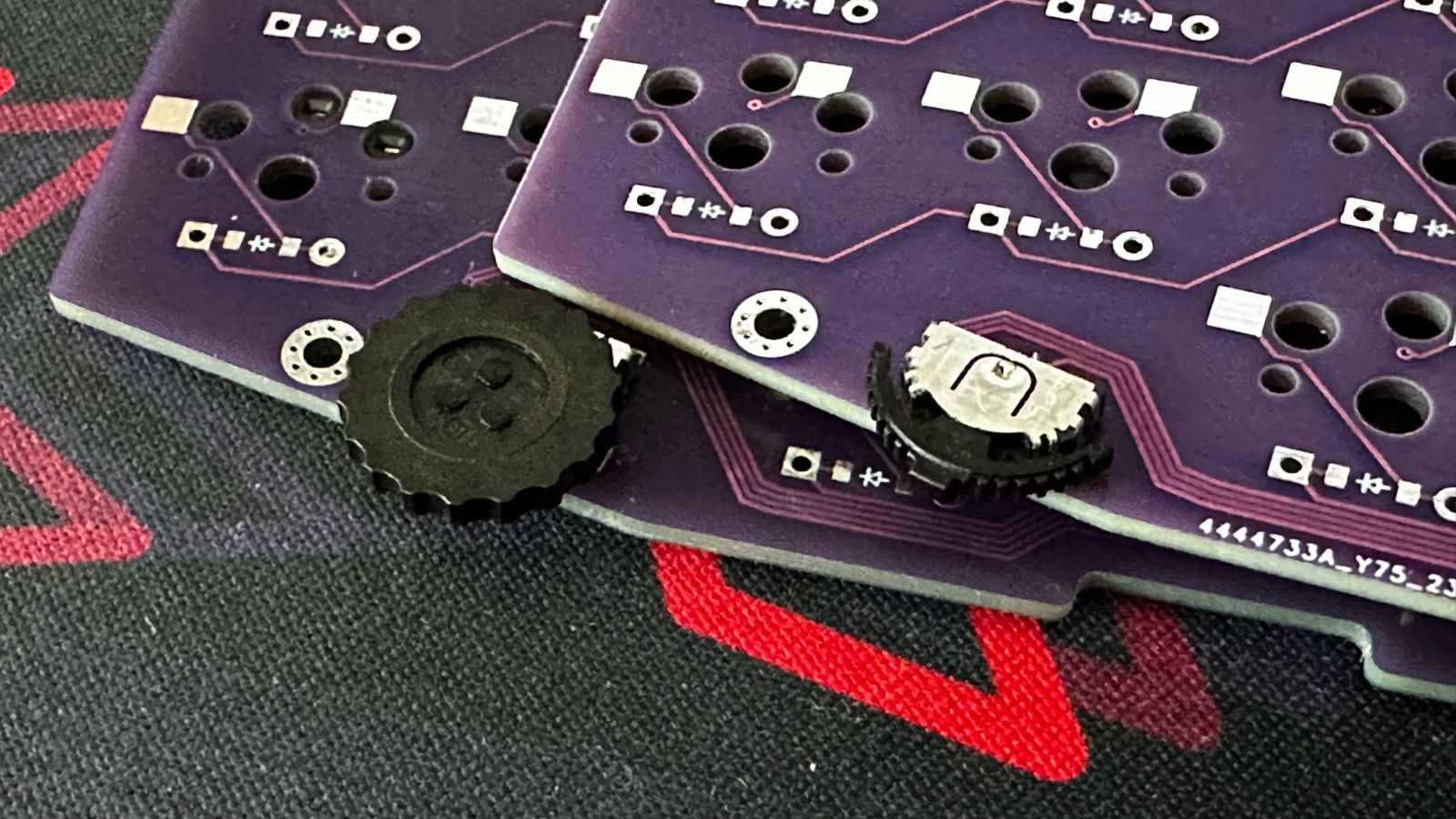
I originally tried working with the SIQ-02FVS3 rotary encoder. It's a true spinning wheel, but retains a push action so you can still send three signals like a traditional rotary encoder. Unfortunately I couldn't quite get it working with ZMK. I may have just had a bad batch of encoders, but I eventually swapped it out for a SLLB510100 thumb switch. Instead of a fully spinning knob, this thumb switch allows you to slide it to the left or right by several degrees, or to push in on the center of the switch. It's similar to controls you may have seen on 90s CD players or early 00s MP3 players. It's not a perfect fit for the Game Boy aesthetic, but it's close enough. They're also just a nice touch on low profile keyboards in general. I'll be experimenting a bit more with these in the future.
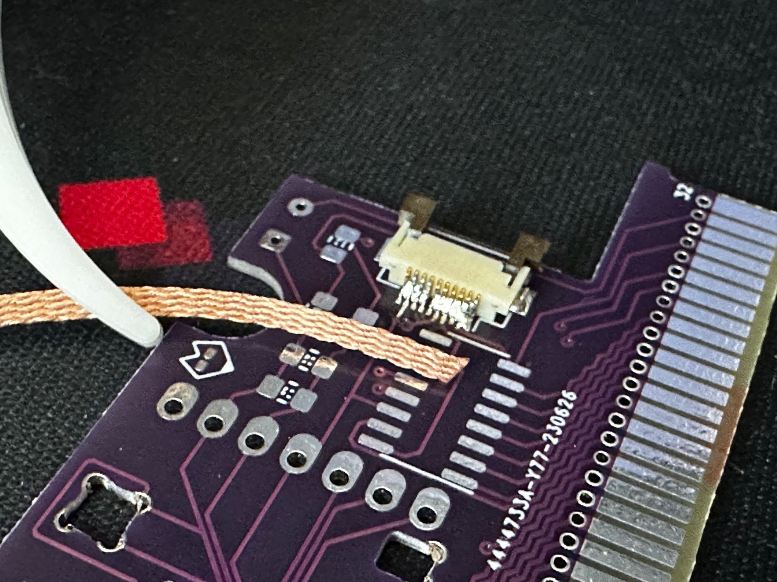
That's it for the hardware. The rest of the TypeBoy is a fairly standard Choc-spaced Sofle derivative with some splay on the last two columns for a bit of flair. Adding the cartridge slot and the thumb switch was more than enough experimentation for one build. You may have noticed a bodge wire in some of the pictures. There was one last wiring issue which I've already resolved in the files hosted on the TypeBoy's GitHub repository, but I didn't want to wait for another batch of PCBs to fix it.
Now that I've got a working keyboard, the last part of this build was to create an enclosure for it. (Note to self: Take more pictures during the bare PCB step!)
The TypeBoy Case
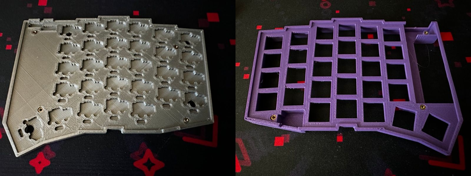
My previous two keyboards have both used a "tray" style 3D printed case. These cases are great for adding a bit of color to your keyboard and protecting the hotswap sockets, but I wanted to do something a little different this time around.
I knew I was going to be leaning specifically into the Game Boy Advance aesthetic. In addition to the whole cartridge thing, I also just picked up some some custom retro purple keycaps from FK Caps. (You can learn more about them in my recent writeup.) With this in mind, I also wanted to try and obscure the Choc Red Pro switches I was re-using from my last keyboard build. The ChonkV leaned into the red accents, but they'd clash a bit here.
To that end I took some inspiration from GEIST's full-height low-profile keyboard cases. Having the edges of the case come right up to the top of the keycaps is a striking look and it would do a good job of mostly obscuring the bright red switches.
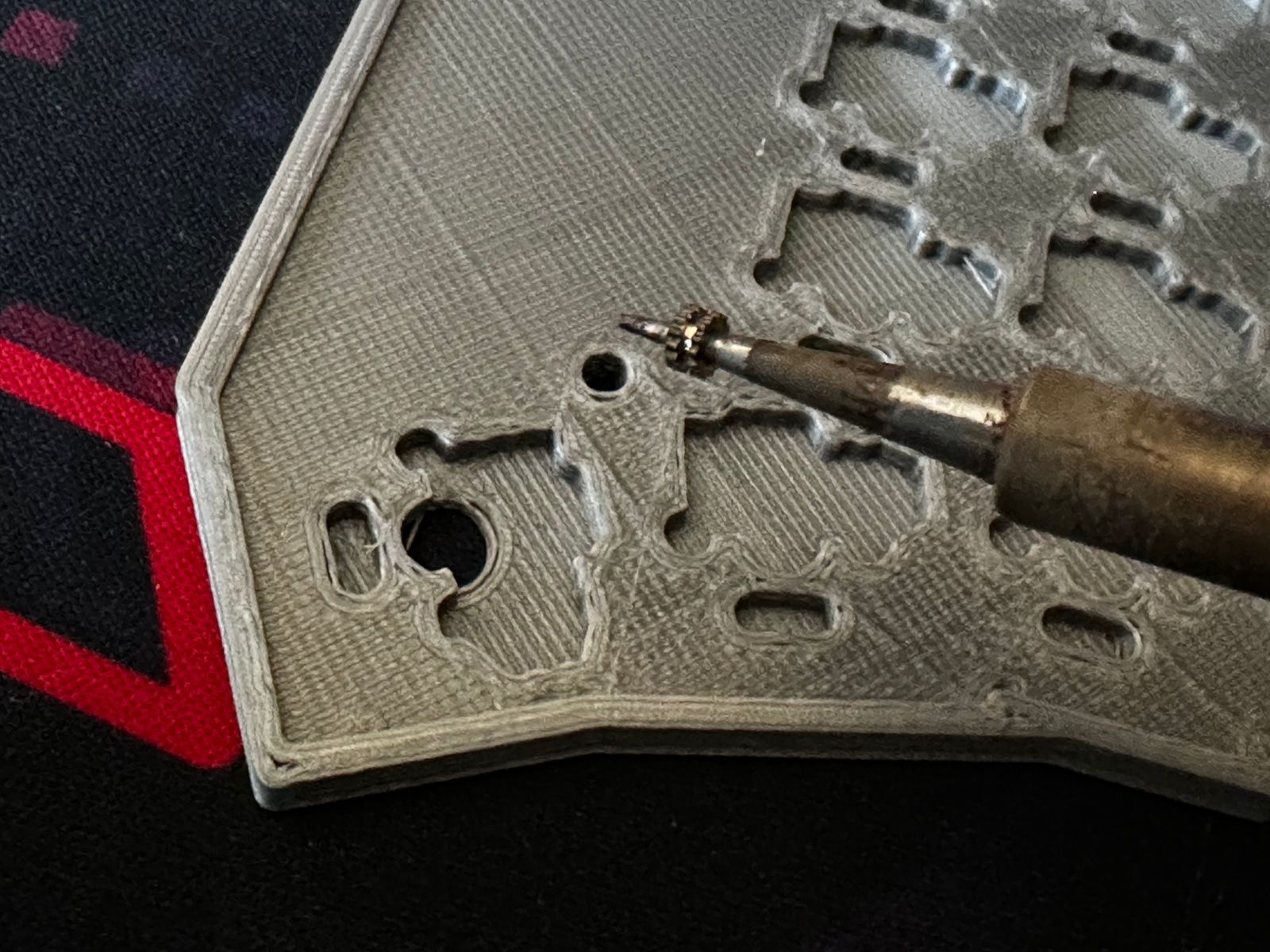
This case design is a little more complicated than what Ergogen can output on its own. I re-learned Autodesk Fusion 360 and ended up building the board in two pieces: The standard bottom tray and a single piece for the top. The top piece needed to be printed upside down for a variety of structural reasons, which means that the portion the keys slot into was left a little gnarly from the temporary supports. You don't see most of these rough spots when the keyboard's finally built.
I'm not completely sure how I feel about the end result here. I knew my TypeBoy's PLA case wouldn't look as nice as the resin-printed cases GEIST used on the Totem keyboard, but the current Texas heat wave gave me a lot more trouble than I expected while printing off this case design. I ended up giving the TypeBoy a duo-tone look with a gray bottom piece for the simple reason that I ran out of purple PLA during my prototyping. Thankfully this is the easiest to swap out component if I decide I'd like to try and take another go at it. I'd still like to experiment with this full-height low-profile case style in the future, but I might also take a break from 3D printing and try some FR4 PCB sandwiches next time. Stay tuned.
Tricky printing aside, the TypePak and TypeBoy are officially done! Now all that's left is to program it.
The Firmware
After all the sturm und drang about cartridge slots and edge connectors, the firmware for the TypePak is relatively standard. It leverages ZMK since this is a wireless keyboard, but otherwise it's not pulling any unusual software tricks. As far as the firmware is concerned, it doesn't know that it's living on an odd removable daughterboard.
In case you're trying to build a keyboard with similar hardware, there's a few noteworthy aspects of this particular firmware build. First of all, it leverages a 74HC595 shift register to give the microcontroller a few extra pins. Next, it has the same LS011B7DH03 display as the Nice!View, but it doesn't actually actually use the Nice!View's wrapper. From the best I can tell, the Nice!View code is designed to pair with the Nice!Nano microcontroller, and things don't map up perfectly if you try running it on a different board.
Both of these bits of code are just serial device definitions. The screen uses ZMK's built in display support. The shift register meanwhile isn't too tricky to work with. Once you define the register, you can use it's pins as columns in a matrix just like you would with a standard microcontroller GPIO pin.
The only other piece of hardware on the TypeBoy is the thumb switch. It's wired up like three standard pushbuttons with a common ground, so it's not hard to get running in ZMK. You just define a "Composite" key scan driver that uses a standard keyboard matrix for the keys themselves, and then a direct wiring setup for the thumb switch "buttons".
ZMK is pretty well documented in the site's getting started guide. If you'd like to poke around any of the aforementioned code, you can check out the TypePak's ZMK config on GitHub.
With that, we've finally got a fully functioning keyboard! Which begs a question.
Why Go To All This Trouble?
Surely there must be some reason I'm going to all these lengths, right? The TypePak and TypeBoy must offer some sort of benefit that you don't get from your standard mechanical keyboard build?
Not particularly? The XIAO BLE and a bare Sharp Memory Display module are cheaper than a Nice!Nano and Nice!View, but it's a wash when you factor in the other support hardware. The classic Pro Micro stack just needs some header pins. The TypePak needs a custom PCB, a cartridge shell, a cartridge slot, a display connector, a shift register, and several surface mount capacitors. Depending on the shipping fees of your suppliers, the TypePak and the Nice! combo cost roughly the same amount.
The components inside of the TypePak occupy a space that's roughly comparable to the traditional microcontroller stack, but the cartridge connector and the TypePak itself takes up considerably more room. It's fine for designs where the cartridge can hang off the side of the keyboard like the TypeBoy, but it might not fit every build.
One of the strengths of the TypePak is how easy it is to move from one keyboard to another. The mechanical keyboard community is particularly fond of machine pin headers, but I personally feel like I'm going to break them every time I try inserting or removing a microcontroller that's using diode legs. This ease of moving a TypePak between keyboards is nice, but it's slightly hampered by the reality of firmware logistics. If you move from a 6x4+5 split keyboard to a 5x3+3 split keyboard, or from a split keyboard to a unibody build, you're most likely going to need a different keymap. The act of slotting the TypePak in will take two seconds, but you'll still have to re-flash the microcontroller for the new layout.
So... That mostly just leaves aesthetics and the hardware challenge. 3D printed case issues aside, I'm really happy with how the TypePak and TypeBoy turned out on the aesthetics front. The cartridge slots in exactly how you'd want it to, and the window on the TypePak is the perfect size for the display. The transparent cartridge really leans in nicely to those early aughts vibes, even if you don't go for the Atomic Purple version.
I'm looking forward to leveraging these TypePaks for my next few keyboard builds. Now that the TypePak is actually built, it's just a couple of dollars per-keyboard for a new Game Boy cartridge slot.
TypePak Build of Materials
| Part | Amount | Price |
|---|---|---|
| TypePak PCB Via JLCPCB | 1 Five Pack | $2.00 USD |
| XIAO nRF52840 | 1 | $10.00 USD |
| HFK110CT-ND Display Connector | 1 | $1.35 USD |
| 560PF Capacitor | 1 | $0.15 USD |
| 1UF Capacitor | 2 | $0.10 USD |
| 300 OHM Ferrite Beads | 2 | $0.20 USD |
| SN74HC595 Shift Register | 1 | $1.00 USD |
| LS011B7DH03 Sharp Memory Display | 1 | $15.00 USD |
| 401020 LiPo Battery (80 mAh) | 1 | $7.00 USD |
| Game Boy Advance Cartridge Shell | 1 | $3.50 USD |
The above table represents the parts needed to construct a single TypePak. You'll need to double everything except for the PCB order if you plan on making two. (JLCPCB fabricates PCBs in groups of 5 as a minimum.) If you're building two TypePaks, it's probably worth bumping the capacitor and ferrite bead orders up to 10. You don't want to have your entire project get stalled if you misplace one of the small components, and the bulk ordering pricing makes buying 4-6 units approximately the same cost as 10.
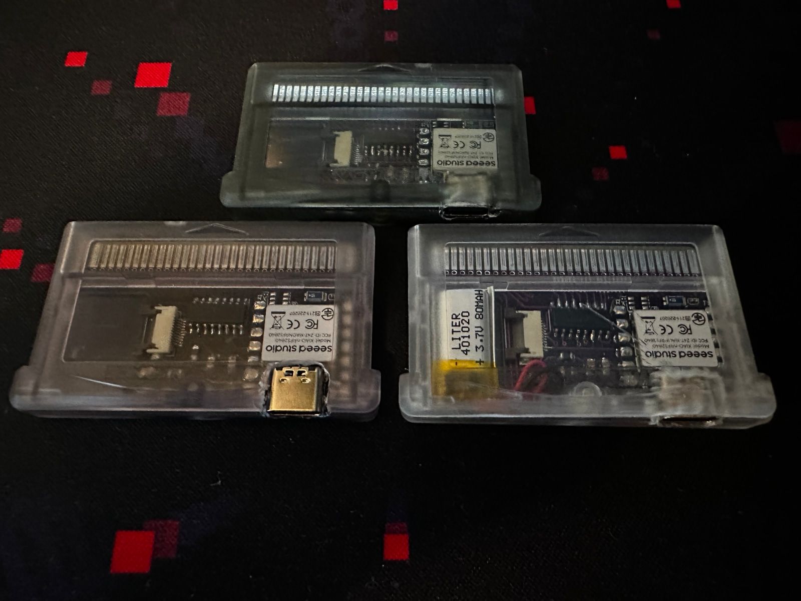
There's a variety of aftermarket Game Boy Advance cartridges available online. They primarily come in two varieties: Ones with small plastic dots on the inside of the label window, and those that don't. Make sure you get the version with the completely clear window. So far I've tested the TypePak with the gray "smokey" clear, Atomic Purple, and standard clear casings. The Sharp Memory Display is clearly visible through all of them. I assume they'd be similarly visible through the transparent red and transparent blue cases on the market.
One small note, most cartridge vendors mention that they're designed for "bootleg" PCBs. Authentic Game Boy Advance cartridge PCBs and shells have two small tabs on the inside to hold the PCB in place. These tabs aren't completely necessary, and they take up space that you could otherwise use for parts. The TypePak uses the "bootleg" PCB footprint and won't fit inside of an authentic cartridge. Don't be a monster and try to drill into a functioning Game Boy cartridge. These cartridge shells are cheap, widely available, and come in plenty of different colors.
TypeBoy Build of Materials
| Part | Amount | Price |
|---|---|---|
| TypeBoy PCB Via JLCPCB | 1 Five Pack | $20 USD (Incl. Slow Shipping) |
| Game Boy Cartridge Slot | 2 | $5.00 USD |
| SLLB510100 Thumb Switch | 2 | $8 USD |
| Right Angle Pushbutton | 2 | $1.00 USD |
| Right Angle Switch | 2 | $1.50 USD |
| Choc Hotswap Sockets | 58 | $12.00 USD |
| 1N4148 T4 Diodes | 58 | $3.00 USD |
| Choc Switches | 58 | $28.00 USD |
| Choc Keycaps | Alphas + Mods | $60.00 USD |
| 3D Printed Case | Buy Your Buddy Some Filament | $20.00 USD |
| Bumpons | 1 Pack | $10.00 USD |
As I mentioned earlier, I've generally found machine pin headers a bit too fiddly for my taste. The dream of DIY mechanical keyboards is that you can just move the expensive parts from socket to socket and keep your build costs low. Despite this, my Pro Micros have stayed put on my original Sofle, and my Nice!Nano is firmly planted on my ChonkV. The TypePak seems much more likely to see some movement between boards however.
If that dream becomes a reality, one of the TypePak based keyboards should run you about $50 USD when all is said and done. You still need to drop about $80 USD on the TypePaks, between $30-50 USD on switches, and another $50-70 USD on keycaps. Once you've done that upfront cost however, iterating on designs and rapid prototyping should be a bit less taxing on one's budget. More or less, depending on your access to a 3D printer and how many bumpons you've got clogging up your project drawer.
Acknowledgements
The TypeBoy isn't the first mechanical keyboard which takes microcontroller cartridges. mujimanic's Giga40 keyboard design and it's Famicom cartridges helped prove a low-profile Game Boy-centric version of this idea was worth pursuing.
The TypePak's display connector circuit is based off of karnadii's Sharp Memory Display breakout board design. The TypePak's PCB is based off of templates from djedditt's kicad-gamepaks library. The Game Boy cartridge slot KiCAD footprint was used from Martin Refseth's Game Boy KiCad Library.
As usual, thanks to the Absolem Club Discord and their #Ergogen channel for answering my endless onslaught of questions. Particularly special thanks to Pete Johanson for assisting with some ZMK troubleshooting when the low profile rotary encoders were giving me trouble. The ZMK firmware is heavily influenced by previous configs by GEIST, Pete Johanson, and JonMuller.
This keyboard is another derivative of Josef Adamčík's original Sofle Keyboard layout. I need to start experimenting with other layouts at this point, but it's hard to beat that thumb cluster.
Finally, another shout out to GEIST, Freya, Bubbleology for their work on the TOTEM keyboard's case. It was a big inspiration for this build, and they pulled the concept off way better than I did.
Conclusion
I still can't believe this worked. Right up until it started typing, I felt like I bit off a bit more than I could chew with this particular design. It was my first XIAO BLE build, my first LS011B7DH03 breakout board build, my first time experimenting with thumb wheels, and my first time trying to cram everything inside of a Game Boy cartridge. I'm a little astonished it all managed to come together. Part of me was worried this would just get written off as some dead end surface mount soldering experience.
A few people have asked me if I'm going to try and establish the TypePak as a "standard" of some sort that designers build a keyboard around. We'll see how much interest there is in this particular build, but right now I think this is probably going to be relegated to exceptionally nostalgic do it yourselfers. The Dremel step of, "Carve away plastic until it feels about right" is a little too vague for a true guide at the moment, and right now these cartridges have a 50% rate of accidentally smashing the most expensive $15 USD part in the build. We'll see where things go in the future.
For now I'm happy to get some typing in on my new keyboard. You can bet I'm already thinking about where I'll take things next. Until then, you can view all of the KiCAD files, Ergogen configs, and ZMK keymaps for the TypePak and TypeBoy on GitHub. As always, feel free to give me a shout out on Mastodon if you liked this project!